Pakistan Dams Information

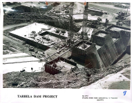
August 11, 1971.
Concreting
Intake No . 1

1788533372441.png
 
April 1971
No. 2

1788533561163.png
 
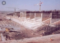
Two superb comparison pics of the Main Spillway taken almost 50 years apart. The first pic is from the NANCY MUDRON album taken by her Dad, MILTON MUDRON in late 1965.

On the slide he wrote: "Looking southeast down the Lower Stilling Basin & future channel to Jhelum River. Nothing like this in the world." The second pic is from the A. AHMED KHAN album: Upper Stilling Basin – Main Spillway. September 5, 2014.

(Pic credit Mr. Arshad)

1788534043916.png


1788534084464.png
 
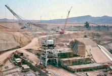
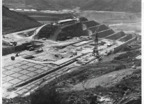
Excellent pic from the BOB FISH album. FROM BOB:..

..1965, Main spillway weir & lower stilling basin construction. Mangla Dam embankment slope in back. Concrete lifts on the left side of lower stilling basin slope are being serviced by the red Manitowoc 4600 crane setting on shoulder of access road.

Note the large slabs of concrete used for counter weight on the back of the American whirley crane cab. Without these counter weights the crane could not handle the heavy lifts that it does.....ie an eight cubic yard bucket full of concrete.

1788534180698.png
 
1788534240804.png

Mangla Dam
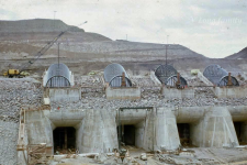
Wonderful 1960’s pic from the V.L.LONG album. FROM LILLIAN: Tunnel Intakes. BOB FISH added - Intake concrete is done.........trash screens are in place and embankment above intake is ongoing.........
 
1788534469723.png


1788534488382.png


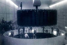
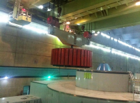
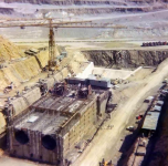
Two wonderful comparison pics taken in Mangla Power House 50 years apart.
The first 1960’s pic is from the TOM APPLEBY(Dad) album: Historical pic of the installation of Unit No. 1, Mangla Power House.
The second pic is from the ALI IMRAN album first posted in 2015: Mangla Power House.
 
1788534591114.png


Mangla Dam Equipment -

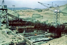
Amazing pic from the McCALLISTER FAMILY album. FROM MARSHA: Headworks of the Main Spillway construction. BOB FISH gave us the following description - Base slabs & beginning of piers of Main Spillway Headworks.

This is such a good photo as it shows the first of the trunnion girder cable anchorage frames in place. The cables were anchored in the bottom back of the piers to hold firm the gate trunnion bearings. After pier concrete was placed and cured these cables & anchorage were stressed to a required dimension to assure they would do the job.
 
Tarbela Dam

1788621926987.png


1788621948013.png


1788621979068.png
 
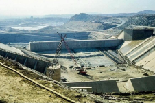
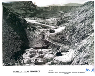
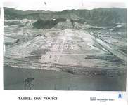
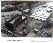
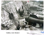
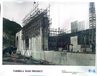
Tarbela Dam 1970's

1788622022200.png


1788622093535.png
 
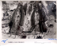
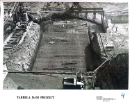
1971

1789561619364.png
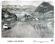
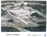
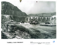
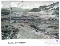
11 August 1971 .. Auxiliary Dam No. 1
 
This image appears to be an important historical image from the early days of the construction of the Tarbela Dam Project. According to the text below, it is related to the Auxiliary Dam area and dates back to August 28, 1971.

Auxiliary Dam Area
This shows one of the auxiliary dams in the Tarbela project, built to fill the area on the left side.

In the foreground, a large earthfill/rockfill structure is visible.
This was part of the earth-fill/rockfill construction. The main dam of Tarbela is also a very large embankment dam of this type.

Heavy construction machinery
On the right, a large construction vehicle is visible, likely used for transporting or constructing soil or stones.

In the middle, construction activity and machinery traces can be seen.
On the left, a steel structure
A tall lattice steel tower is visible on the left side of the image, with a fixture/light or construction supervision equipment installed on it.

This may be a temporary facility or lighting arrangement in the construction area; it is not possible to determine its exact use from the image alone.

Mountainous area

In the background, the mountains around Tarbela are clearly visible.
At that time, the area was a completely different landscape compared to the Tarbela Reservoir today.
1789845801988.png
 

Users who are viewing this thread

  • Pakistan Defence Latest

    Back
    Top